
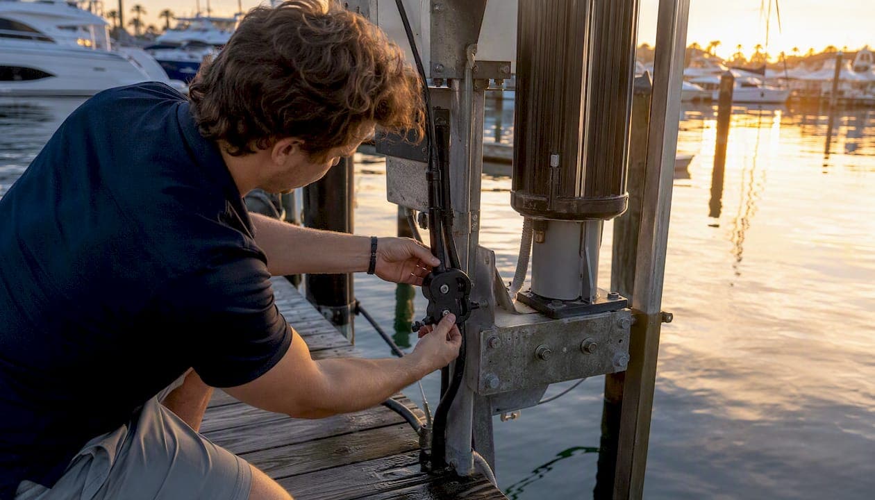
The most effective IoT sensor integration pattern for boat lifts combines current sensors, limit switches, and a position encoder on each motor with a marine-grade edge gateway that forwards telemetry to your marina management platform. Deploy that stack on one to three lifts as a pilot, validate your alert thresholds over 30–90 days, then roll out site-wide. The payoff is direct: fewer emergency shutdowns, remote fault diagnosis, and predictive maintenance that converts reactive repair calls into scheduled service windows.
Start your pilot with these four elements:
- Sensors: current sensors and limit switches at minimum; add load cells or encoders for advanced position tracking
- Gateway: a cellular or LoRaWAN gateway with marine-grade enclosure rated IP66 or better
- Controller interface: a retrofit controller or auxiliary relay board that mediates between sensors and existing high-voltage lift circuits
- Marina software integration: a platform that ingests lift telemetry and converts alerts into maintenance tasks and billing triggers
Pro Tip: Before ordering hardware, walk every lift and document its motor amperage rating, existing control wiring, and enclosure location. That 30-minute audit will prevent mismatched sensors and wiring surprises on installation day.
Key Takeaways
IoT sensor integration for boat lifts delivers the highest ROI when current sensing, cycle counting, and a marine-grade cellular or LoRaWAN gateway are deployed together and connected to a marina management platform that automates alerts into maintenance tasks.
| Point | Details |
|---|---|
| Start with the minimum viable sensor set | Current sensor plus cycle counter and battery-voltage monitor covers most early-fault detection needs at the lowest cost. |
| Choose connectivity before hardware | Survey cellular and LoRaWAN coverage at every dock section before ordering sensors; a hybrid cellular gateway with BLE or LoRaWAN sensors suits most US marinas. |
| Pilot on your worst lift first | The lift with the most emergency calls teaches you the most and produces the clearest ROI signal for scaling the budget. |
| Build safety in hardware, not software | Power-isolation relays, hardware E-stop, and watchdog timers must stop a lift even when the processor or cloud connection is unavailable. |
| Atlantis Marina closes the loop | Atlantis Marina ingests lift telemetry, creates maintenance tasks, updates billing, and notifies staff via mobile, connecting sensor data to full marina operations. |
Table of Contents
- Why IoT sensors matter for marina boat-lift operations
- Core sensors for boat lifts and what each one measures in practice
- Connectivity choices and device lifecycle management
- How sensors integrate with boat-lift controllers and relay wiring
- Designing safety, interlocks, and fail-safe behavior for connected lifts
- Practical installation details for the marine environment
- From telemetry to operations: alerts, dashboards, and marina software integration
- Maintenance schedule and long-term lifecycle planning
- Pilot-to-rollout roadmap with timeline and budget
- A concrete example: virtual-limit detection via current sensing
- What does IoT sensor integration actually cost?
- How long does an IoT boat lift project actually take?
- Integrating IoT sensors with legacy boat lift control systems
- Data security and privacy in marina IoT systems
- What most marina operators get wrong about IoT lift integration
- Atlantis Marina connects your lift telemetry to full marina operations
- Sources
- FAQ
Why IoT sensors matter for marina boat-lift operations
A boat lift that fails mid-cycle does not just inconvenience one boater. It blocks a slip, generates an emergency service call, and can damage a vessel if the load drops unexpectedly. Smart marina IoT integration addresses all three risks simultaneously by giving operators real-time visibility into lift health without requiring a technician on-site.
The operational benefits map directly to marina KPIs:
- Safety: current-sensing shutdowns and tilt alerts stop motors before mechanical failure or overload causes injury
- Uptime: remote fault diagnosis cuts mean time to repair because technicians arrive with the right parts
- Predictive maintenance: vibration, temperature, pressure, and load sensors combined with edge analytics convert emergency downtime into planned maintenance windows
- Labor savings: remote monitoring reduces routine site visits, freeing dockmaster staff for higher-value tasks
- Billing accuracy: cycle counts tied to marina software create an auditable usage record that supports per-use billing models
The financial case is straightforward. Emergency lift repairs typically cost two to four times more than planned replacements because of expedited parts shipping and after-hours labor. Predictive maintenance reduces that multiplier by catching degradation early, before collateral damage spreads to gearboxes or motor windings.
Core sensors for boat lifts and what each one measures in practice
The sensor selection drives everything downstream: wiring complexity, gateway bandwidth, and the quality of your predictive models. Start with the minimum viable set, then layer advanced sensors as your data maturity grows.
| Sensor Type | What It Measures | Primary Failure Mode Detected |
|---|---|---|
| Current sensor (CT clamp) | Motor draw in amps | Motor stall, overload, winding degradation |
| Limit switch (mechanical) | End-of-travel position | Over-travel, mechanical binding |
| Rotary encoder / position sensor | Shaft revolutions, lift height | Drift from calibrated position |
| Load cell / strain gauge | Cradle weight in lbs | Uneven loading, overload, structural fatigue |
| Accelerometer / tilt sensor | Platform angle and vibration | Structural misalignment, wave-induced sway |
| Vibration sensor | High-frequency bearing signature | Bearing wear, gear tooth damage |
| Temperature sensor | Motor or gearbox heat | Thermal overload, cooling failure |
| Hydraulic pressure transducer | Fluid pressure (hydraulic lifts) | Seal failure, pump degradation |
| Water / intrusion sensor | Enclosure flooding | Cable seal failure, submersion risk |
| Smart load pin | Shackle or cable tension | Cable fatigue, asymmetric load |
Minimum viable set for most marinas: current sensor plus a cycle counter (derived from current pulses) and a battery-voltage monitor. Cycle counting combined with battery-voltage monitoring gives the highest signal-to-noise ratio for routine lift health and flags motor degradation before failure.
Advanced predictive maintenance layer: add vibration sensors and load cells once you have baseline current data. Vibration signatures reveal bearing wear weeks before audible noise appears.
Marine-grade selection criteria: specify IP67 or better for sensors near the waterline, 316 stainless or fiberglass housings for saltwater environments, and tinned-copper conductors with marine-grade heat-shrink connectors throughout.
Pro Tip: Mount current sensors on the load side of the motor-direction relay, not the line side. That placement captures per-motor draw rather than combined panel current, giving you motor-level fault isolation.
Connectivity choices and device lifecycle management
Marina topology rarely favors a single connectivity standard. Covered dry stacks block cellular signal; floating docks move with tide; and marina Wi-Fi is often congested or unreliable for mission-critical telemetry. Smart integrated lift controls require stable connectivity, and choosing the wrong standard is the most common cause of failed pilots.
Connectivity tradeoff summary:
- Wi-Fi (2.4/5 GHz): high bandwidth, low cost per device, but coverage gaps at far docks and interference from boater devices make it unreliable as a sole transport for safety-critical alerts
- Cellular (4G LTE / 5G): reliable coverage at most US marinas, supports OTA updates and video, but carries a monthly SIM cost ($10–$25 per device) and depends on carrier coverage maps
- LoRaWAN: long range (1–5 miles line-of-sight), very low power, low data rate; ideal for cycle counts and battery voltage where you need years of battery life and wide coverage with one gateway
- BLE + gateway hybrid: sensors transmit BLE to a dock-mounted gateway that uplinks via cellular or Wi-Fi; reduces per-sensor cost and power draw while maintaining reliable backhaul
Recommended pattern for most US marinas: deploy LoRaWAN or BLE sensors on lifts, with a cellular gateway per dock section. That hybrid keeps per-lift hardware costs low while providing reliable backhaul independent of marina Wi-Fi.
Device lifecycle essentials:
- Provision each device with a unique X.509 certificate at enrollment; never share credentials across devices
- Use a device management platform that supports OTA firmware updates with staged rollouts (10% of fleet first, then 50%, then 100%) and automatic rollback on failure
- Segment lift controllers on a dedicated VLAN, separate from boater guest Wi-Fi and marina office networks
- Apply tamper-evident seals to enclosures and log any physical access in your maintenance records
How sensors integrate with boat-lift controllers and relay wiring
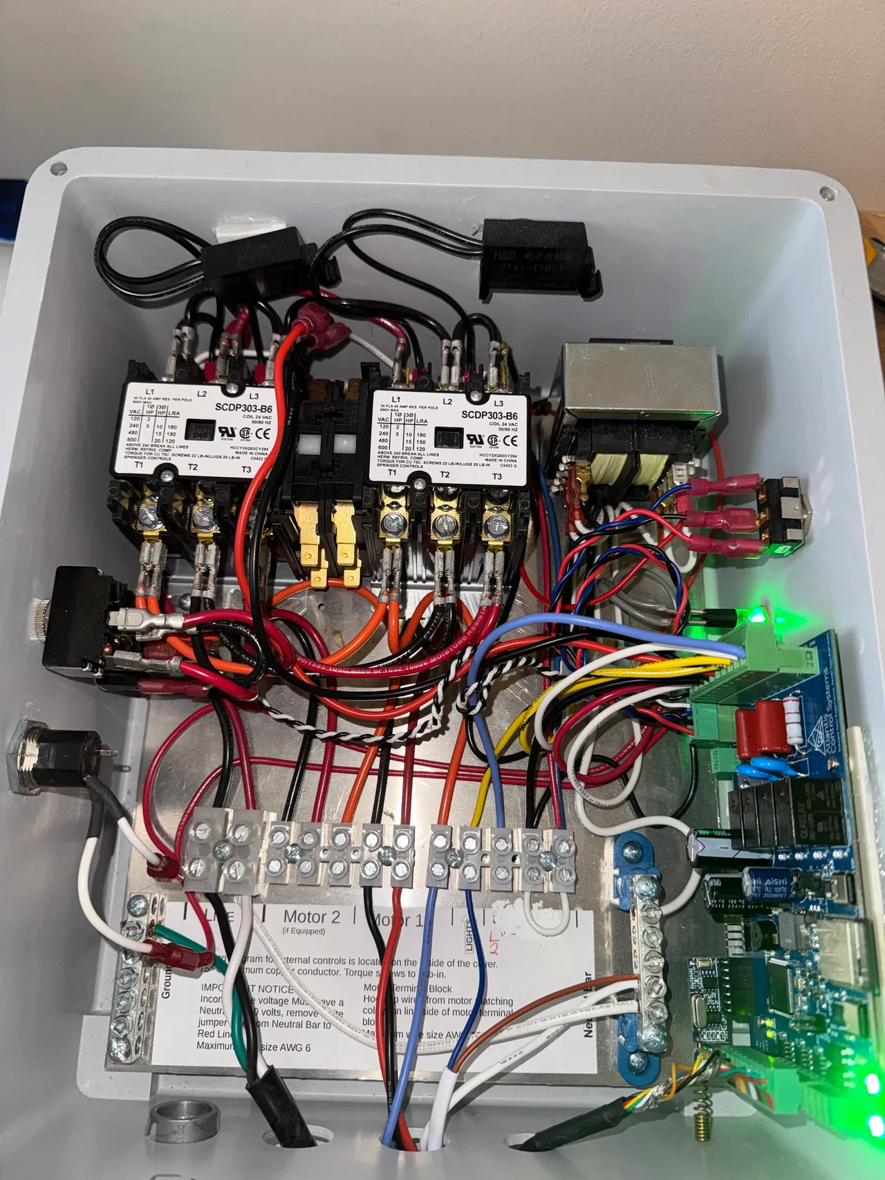
The US11987332B2 boat lift controller patent describes the reference architecture most retrofit controllers follow: a processor board connected to digital switches, power-isolation relays, motor-direction-select relays, and per-motor current sensors. The processor reads current signals to infer lift position and stops motors at virtual limits without mechanical end-stops.
Key control insight: The processor counts motor shaft revolutions derived from current-pulse patterns and compares that count against a calibrated full-travel revolution count. When the count reaches the programmed limit, the processor opens the power-isolation relay before mechanical binding occurs. Excessive current at any point in the cycle triggers an immediate shutdown independent of position count, providing a second layer of protection.
Wiring integration sequence:
- Install current sensors (CT clamps) on the load-side conductors between the motor-direction relay output and each motor terminal
- Connect current-sensor analog outputs to the processor's ADC inputs
- Wire the processor's digital outputs to the coils of the power-isolation relays; the relay contacts sit in series with the motor supply
- Connect motor-direction relays downstream of the isolation relay so direction can only change when the isolation relay is open
- Route all signal wiring in separate conduit from power wiring; maintain at least 6 inches of separation to prevent inductive interference
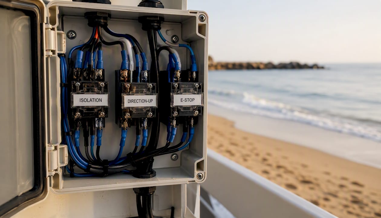
Integrating with legacy controllers: most legacy lift panels have a dry-contact input for an external E-stop or interlock. Wire your retrofit controller's output relay into that dry-contact loop. This lets the IoT controller interrupt power without touching the legacy high-voltage wiring, which simplifies permitting and reduces liability.
AUX device control guides cover digital-relay network wiring for high-voltage lift circuits in detail and are worth reviewing before finalizing your wiring diagram.
Pro Tip: Label every relay with its function (ISOLATION, DIRECTION-UP, DIRECTION-DOWN, E-STOP) using marine-grade heat-shrink labels before closing the enclosure. Unlabeled relays are the single biggest source of troubleshooting delays during commissioning.
Designing safety, interlocks, and fail-safe behavior for connected lifts
Safety architecture is not optional and not a software problem alone. Hardware interlocks must be able to stop a lift even when the processor, gateway, or cloud connection is unavailable.
Mandatory safety elements:
- Hardware E-stop: a normally-closed mushroom-head button wired in series with the motor supply, independent of all software logic
- Power-isolation relay: opens the motor supply circuit on any fault condition; the processor must actively hold it closed, so a processor crash defaults to open (fail-safe de-energized)
- Neutral-interrupt relay: breaks the neutral conductor in addition to the hot, preventing backfeed through ground paths
- Ground-interrupt relay: monitors ground continuity; opens the circuit on ground-fault detection
- Overcurrent protection: hardware fuses or breakers sized to 125% of motor full-load amperage per NEC/NFPA 70 Article 430 requirements
- Watchdog timer: if the processor does not reset the watchdog within a defined interval (typically 5–30 seconds), the watchdog hardware opens the isolation relay
Virtual safety via edge logic:
- Auto-shutdown triggers when motor current exceeds 150% of baseline for more than 500 milliseconds
- Command sanity checks reject any command that would drive a lift past its calibrated travel limit
- Debounce logic requires a fault condition to persist for at least 200 milliseconds before triggering shutdown, reducing nuisance trips from current spikes during motor start
Commissioning safety checklist (document every test for liability records):
- Verify E-stop opens isolation relay within 100 milliseconds of activation
- Simulate overcurrent by reducing the software threshold temporarily; confirm auto-shutdown fires
- Confirm watchdog timer triggers isolation relay on processor reset
- Test virtual upper and lower limits through full travel cycles with a calibrated load
- Verify telemetry records each test event with timestamp and sensor values
For permit guidance, consult your local Authority Having Jurisdiction (AHJ) and reference NEC/NFPA 70 for electrical installation requirements. NOAA's marine safety publications provide additional context for waterfront electrical installations. This article provides general technical guidance, not legal or code compliance advice.
Practical installation details for the marine environment
Marine environments are hostile to electronics. Salt air corrodes terminals in months; UV degrades cable jackets; and tidal movement stresses conduit connections. Getting the physical installation right is as important as the sensor selection.
Enclosures and materials:
- Use polycarbonate or fiberglass enclosures rated IP66 minimum; IP67 for locations below dock level or subject to spray
- Stainless steel hardware only for mounting; galvanic isolation washers where stainless meets aluminum structure
- Apply conformal coating to all PCBs inside enclosures before sealing
Cabling and routing:
- Separate power and signal conduit runs by at least 6 inches; use metallic conduit for power runs near motors
- Marine-grade tinned-copper conductors (ABYC E-11 compliant) throughout; standard copper corrodes at terminal connections within one season in saltwater environments
- Strain relief at every enclosure entry; drip loops on all cable entries to prevent water ingress
Pro Tip: Run a spare conductor pair in every conduit run during initial installation. Adding a sensor or signal wire later without a spare means pulling new conduit, which costs far more than the extra wire at installation time.
Power options:
- Local mains via pedestal: most reliable; use a dedicated 20A circuit with GFCI protection per NEC 553 for marina wiring
- Battery-backed controller: a 12V sealed AGM battery with a trickle charger keeps the controller and gateway alive during shore-power outages; size for 24–48 hours of standby
- Solar-assisted remote sensors: a 10–20W panel with a charge controller powers LoRaWAN or BLE sensors on remote lifts without running new power conduit
Surge and lightning protection:
- Install a Type 2 surge protective device (SPD) at the pedestal panel feeding each lift circuit
- Add a secondary SPD at the controller enclosure input
- Bond all metallic enclosures to the marina grounding grid per ABYC E-11 and NEC Article 553
From telemetry to operations: alerts, dashboards, and marina software integration
Raw sensor data has no operational value until it becomes a work order, a billing trigger, or a staff notification. The integration flow is: sensors → edge gateway → cloud telemetry → marina management platform → alert → action.
Alerting rules that reduce false positives:
- Set current-overload alerts at 130% of baseline, not 100%; motor inrush current at startup routinely spikes above full-load amperage
- Require three consecutive anomalous readings before escalating to a maintenance alert
- Route critical alerts (E-stop triggered, motor stall) to SMS and push notification simultaneously; route advisory alerts (cycle count milestone, battery voltage low) to dashboard only
Dashboard requirements for facility managers:
- Cycle count per lift per day, week, and month
- Mean time between failures (MTBF) trend by lift model and age
- Next predicted service date based on cycle count thresholds
- Battery voltage trend with projected replacement date
Integration principle: When a lift alert fires in the telemetry layer, the marina management platform should automatically create a maintenance task, assign it to the on-call technician, and flag the slip as "service pending" so reservations staff do not assign it to an incoming boater. That closed loop eliminates the manual handoff that causes delays and double-bookings.
Cloud-based lift control can also integrate meter reading and billing, enabling remote power toggling and usage-based service charges tied directly to lift cycle data.
Atlantis Marina's smart lift control platform ingests lift telemetry, generates maintenance tasks, and updates billing and occupancy records automatically. Mobile alert configuration for lift telemetry covers threshold setup and escalation paths in detail.
Maintenance schedule and long-term lifecycle planning
Sensors and controllers need their own maintenance cadence, separate from the mechanical lift service schedule.
Suggested maintenance schedule:
- Daily/weekly (visual): inspect enclosure seals, check indicator LEDs, confirm gateway uplink status on dashboard
- Monthly (telemetry review): pull cycle count trends, review battery voltage curves, check for alert frequency changes that signal developing faults
- Quarterly (calibration): re-run full-travel calibration cycles; verify current-sensor zero offset; clean enclosure vents and inspect cable strain reliefs
- Annual (replacement window): replace any sensor showing drift beyond 5% of calibrated baseline; inspect and re-torque all terminal connections; update firmware to current stable release
OTA update process:
- Test every firmware release on one lift for 72 hours before fleet-wide deployment
- Maintain a rollback image on the device; if the update fails health checks within 24 hours, the device reverts automatically
- Log every OTA event with timestamp, firmware version, and device ID in your maintenance records
Lifecycle cost planning: current sensors and limit switches typically last 5–7 years in marine environments with proper enclosures. Gateways and processor boards run 3–5 years before firmware support ends. Budget for a full controller refresh every five years and sensor spot-replacements annually.
Pro Tip: Keep a labeled spares kit on-site with one of each sensor type, a spare gateway, and a spare relay board. Cross-reference every spare to its installation record by serial number. When a sensor fails at 7 PM on a Friday, you want to swap it in 20 minutes, not order it Monday.
Pilot-to-rollout roadmap with timeline and budget
A structured pilot on one to three lifts is the lowest-risk path to site-wide deployment. Smart boat lift automation guides cover enterprise-scale deployment patterns in detail; the framework below is sized for a marina operator running their first IoT project.
Phase breakdown:
- Planning (weeks 1–2): site audit, lift inventory, connectivity survey, sensor selection, wiring diagram review, permit pre-application
- Procurement (weeks 3–4): order sensors, gateway, retrofit controller, enclosures, cabling, and surge protection; confirm lead times
- Pilot installation (weeks 5–6): install on 1–3 lifts, wire sensors, commission controller, connect gateway, configure alerts in marina software
- Evaluation (weeks 7–18, 30–90 days of operation): collect baseline data, measure alert accuracy, track maintenance labor saved, document any wiring or threshold adjustments
- Scaled rollout (weeks 19+): apply lessons from pilot, deploy remaining lifts in batches of 5–10, update documentation and training
Budget line items to plan for:
- Current sensors and limit switches: $50–$150 per lift
- Load cells or encoders (advanced): $200–$500 per lift
- Retrofit controller or relay board: $300–$800 per lift
- Marine-grade gateway (cellular or LoRaWAN): $200–$600 per gateway (covers 10–20 lifts)
- Enclosures, cabling, connectors, surge protection: $150–$400 per lift
- Installation labor: $400–$1,200 per lift depending on wiring complexity
- Cellular SIM or LoRaWAN network subscription: $10–$25 per month per gateway
- Marina software integration services: $500–$2,000 one-time setup
Pilot success criteria (go/no-go for scale):
- False alarm rate below 5% of total alerts over the evaluation period
- At least one early-fault detection event documented before mechanical failure
- Maintenance labor per lift reduced by a measurable amount versus pre-pilot baseline
- Telemetry data flowing reliably to marina management platform with less than 1% data loss
A concrete example: virtual-limit detection via current sensing
This example ties together the sensor, wiring, algorithm, and commissioning steps for a single-motor vertical boat lift retrofitted with a current-sensor virtual-limit system.
System architecture:
- One CT clamp current sensor on the load-side motor conductor, outputting 0–5V analog to the processor ADC
- One retrofit controller board with power-isolation relay, direction relay, watchdog, and cellular gateway module
- Gateway uplinks to cloud telemetry; Atlantis Marina ingests alerts and creates maintenance tasks
Virtual-limit algorithm:
- At commissioning, run the lift from full-down to full-up with a calibrated load; record the total revolution count (derived from current-pulse frequency) as
R_max - Set the upper virtual limit at
R_max × 0.97to provide a 3% safety margin before mechanical end-stop contact - During operation, the processor increments a revolution counter on each current pulse; when the counter reaches the upper limit, the isolation relay opens
- If motor current exceeds 140% of the baseline running current at any point, the isolation relay opens immediately regardless of position count
Commissioning checklist:
- Baseline run: record full-travel current profile and revolution count with rated load
- Overload simulation: add 10% above rated load; confirm auto-shutdown fires before mechanical binding
- E-stop test: activate hardware E-stop at mid-travel; confirm relay opens within 100 milliseconds
- Telemetry validation: confirm each test event appears in the marina management dashboard with correct timestamp and sensor values
- Operator training: walk dockmaster staff through the alert dashboard, escalation paths, and manual override procedure
From the field: Deployments following this architecture, as documented in the needCode IoT boat lift modernization case study, show that combining firmware redesign with hardware telemetry delivers measurable business value, including faster fault response and documented revenue impact for the facility. The case study reports that replacing legacy embedded hardware with a connected controller and mobile app produced outcomes across maintenance, operations, and customer experience simultaneously.
Cycle counting plus battery-voltage monitoring remains the highest-value practical sensor combination for standard marina lifts, flagging motor degradation before failure and feeding both maintenance and billing workflows.
Pro Tip: After commissioning, run 10 consecutive full-travel cycles with rated load and log the current profile for each. Save that baseline file. Every future anomaly is measured against it, so a clean baseline is the foundation of your entire predictive maintenance program.
What does IoT sensor integration actually cost?
Costs vary by lift type, site complexity, and the connectivity standard you choose. The ranges below reflect typical US marina retrofit projects in 2026.
Per-lift hardware costs:
- Minimum viable sensor set (current sensor, cycle counter, battery monitor): $100–$250
- Retrofit controller with relay board and enclosure: $400–$900
- Advanced sensors (load cell, vibration, encoder): add $300–$700 per lift
- Cabling, connectors, conduit, surge protection: $150–$400
Gateway and connectivity (shared across multiple lifts):
- Cellular gateway covering 10–20 lifts: $300–$600 hardware plus $15–$25/month SIM
- LoRaWAN gateway with similar coverage: $200–$500 hardware; network subscription varies by provider
Installation labor:
- Simple retrofit on a modern lift with accessible wiring: $400–$700 per lift
- Complex legacy panel with custom relay integration: $900–$1,500 per lift
Software and integration:
- Marina management platform integration (one-time): $500–$2,000
- Ongoing platform subscription: included in marina software contract for platforms like Atlantis Marina
Total pilot cost (3 lifts, cellular gateway, minimum viable sensors): approximately $4,000–$8,000 all-in, including labor. A full site of 30 lifts with advanced sensors runs $40,000–$90,000 depending on complexity, with per-lift costs declining as the gateway and integration costs are amortized across more devices.
How long does an IoT boat lift project actually take?
Realistic timeline from planning to validated deployment:
- Weeks 1–2: site audit, connectivity survey, sensor and controller selection, wiring diagram review, permit pre-application
- Weeks 3–4: hardware procurement (allow for 2–4 week lead times on specialty marine-grade components)
- Weeks 5–6: pilot installation and commissioning on 1–3 lifts
- Weeks 7–18: evaluation period (30–90 days minimum to collect meaningful baseline data and validate alert accuracy)
- Weeks 19–30: scaled rollout in batches, incorporating lessons from pilot
Total elapsed time from decision to site-wide deployment: 6–8 months for a 20–50 lift marina. A single-dock pilot can reach validated operation in 8–10 weeks if hardware arrives on schedule and the permit review is straightforward.
The evaluation period is non-negotiable. Alert thresholds calibrated on day one will generate false positives until you have two to four weeks of operational current profiles across different load conditions, ambient temperatures, and tidal states.
Integrating IoT sensors with legacy boat lift control systems
Legacy lift panels present the most common and most underestimated challenge in marina IoT projects. Many lifts installed before 2015 use proprietary relay logic with no digital interface, no labeled terminal blocks, and wiring diagrams that exist only in a retired technician's memory.
Common legacy challenges and practical solutions:
Challenge: no dry-contact interlock input on the legacy panel. Solution: install an auxiliary relay in series with the motor supply, wired from the outside of the panel. The IoT controller drives the auxiliary relay coil; the relay contacts interrupt the motor circuit without touching the legacy wiring. This approach requires only that you identify the motor supply conductors, not that you understand the full legacy logic.
Challenge: unknown motor amperage rating (no nameplate or faded label). Solution: clamp-meter the motor at startup and at full load during a manual test cycle. Use the measured full-load amperage to size your current sensor and set your overload threshold. Document the measured values as the de facto nameplate data.
Challenge: legacy panel uses 240V single-phase with no neutral, making ground-fault detection difficult. Solution: install a ground-fault circuit interrupter (GFCI) breaker at the panel feeding the lift circuit. This provides code-compliant ground-fault protection without requiring access to the legacy panel internals.
Challenge: no cellular or LoRaWAN coverage at a remote dock section. Solution: deploy a LoRaWAN repeater or a directional cellular antenna on a dock post. A single repeater can extend LoRaWAN coverage by 500–1,500 feet in a marina environment with obstructions.
Challenge: firmware and hardware both need replacement (common in lifts older than 10 years). The needCode modernization case study documents exactly this scenario: replacing legacy embedded hardware alongside firmware redesign is often the only path to reliable telemetry, and it delivers measurable business value that justifies the higher upfront cost.
Data security and privacy in marina IoT systems
A marina IoT network connects operational technology (lift motors, relays) to information technology (cloud platforms, billing systems). That convergence creates attack surfaces that standard marina IT security does not address.
Key security measures for marina IoT deployments:
- Device identity: provision each controller and gateway with a unique X.509 certificate; revoke certificates immediately when a device is decommissioned or stolen
- Transport encryption: require TLS 1.2 or higher for all device-to-cloud communication; reject any device that cannot negotiate a current cipher suite
- Network segmentation: place lift controllers on a dedicated VLAN with firewall rules that allow only outbound telemetry to the cloud endpoint; block all inbound connections from the public internet to device IPs
- Physical tamper resistance: tamper-evident seals on enclosures; log any physical access event in the maintenance record
- Data minimization: collect only the sensor data you have a defined use for; do not store raw video or audio from lift cameras longer than your retention policy requires
- Vendor access controls: if your integration vendor requires remote access for support, use a time-limited VPN session with multi-factor authentication, not a permanent open port
Privacy considerations: lift cycle data tied to slip assignments creates a record of when specific boaters use their lifts. Treat that data as personally identifiable under your marina's privacy policy, store it with the same controls as billing records, and disclose its collection in your slip rental agreement.
What most marina operators get wrong about IoT lift integration
The biggest mistake is treating connectivity as an afterthought. Marina operators who select sensors and controllers first, then discover their dock has no cellular signal and the marina Wi-Fi does not reach the far slips, end up retrofitting their retrofit. A connectivity survey on day one costs nothing and prevents that scenario entirely.
The second most common error is underestimating corrosion. A current sensor that costs $80 and lasts seven years in a freshwater inland marina may fail in 18 months in a saltwater environment if it lacks a marine-grade housing. The sensor cost is trivial; the labor to replace it mid-season is not.
Device identity management at scale is the problem nobody thinks about until they have 40 lifts online and need to push a security patch. If you provisioned devices with shared credentials or no certificates, you cannot selectively revoke a compromised device without taking the whole fleet offline. Build certificate-based identity into your provisioning workflow from device one, even if it feels like overkill on a three-lift pilot.
On the positive side, the teams that execute these projects well share one habit: they pilot on their most problematic lift, not their newest one. The lift that generates the most emergency calls is the one with the most to teach you about failure modes, and the one where early-fault detection delivers the clearest ROI signal to justify the scaled rollout budget.
Atlantis Marina connects your lift telemetry to full marina operations
Sensor data sitting in a standalone dashboard does not run a marina. Atlantis Marina's smart lift control platform connects lift telemetry directly to the operations workflows your staff already uses: alerts generate maintenance tasks, cycle counts feed billing records, and slip status updates automatically when a lift goes into service mode.
Onboarding follows four steps: connect your gateway to the Atlantis Marina cloud endpoint, map device IDs to slip and vessel records, configure alert thresholds and escalation paths, and activate automated task creation. From that point, a motor overload alert at 2 AM creates a maintenance task, notifies the on-call technician via the Atlantis Boater App, and marks the slip as unavailable, all without a staff member touching a keyboard.
The marina management platform handles reservations, billing, and occupancy in the same system, so lift telemetry and slip management share a single operational record. For marina operators ready to move from a pilot to a full deployment, schedule a demo with the Atlantis Marina team to map your lift inventory to a deployment plan.
Sources
- Patents
- Case study: IoT Solution for Boat Lift Modernization - needCode
- Predictive Maintenance: How IoT is Eliminating Boat Lift Crane Downtime - PRSync
- How to Choose the Best Boat Lift Control System | HydroHoist
- Radian boat lift sensor (MarinaDockage) - MarinaDockage
FAQ
What sensors should a marina install first on boat lifts?
Start with a current sensor and a cycle counter on each motor, plus a battery-voltage monitor on the controller. This combination flags motor degradation before failure and feeds both maintenance scheduling and billing workflows at the lowest hardware cost.
How does virtual-limit control work on a boat lift?
A processor counts motor shaft revolutions derived from current-pulse patterns and opens the power-isolation relay when the count reaches a calibrated travel limit, stopping the motor before it contacts a mechanical end-stop. An independent overcurrent threshold provides a second shutdown layer if the motor stalls at any point in the cycle.
What connectivity standard works best for marina boat lifts?
A hybrid approach works best for most US marinas: LoRaWAN or BLE sensors on each lift transmit to a cellular gateway mounted per dock section. This keeps per-lift hardware costs low while providing reliable backhaul independent of marina Wi-Fi.
How does IoT lift telemetry connect to marina management software?
Sensor data flows from the lift gateway to a cloud telemetry endpoint, which triggers alerts in the marina management platform. Atlantis Marina ingests those alerts to create maintenance tasks, update slip availability, and adjust billing records automatically.
What are the biggest risks in retrofitting legacy boat lift controls with IoT sensors?
The three most common risks are: unreliable connectivity discovered after hardware is ordered, corrosion failure from non-marine-grade sensor housings, and shared device credentials that prevent selective revocation when a device is compromised. Address all three during the planning phase, before procurement begins.